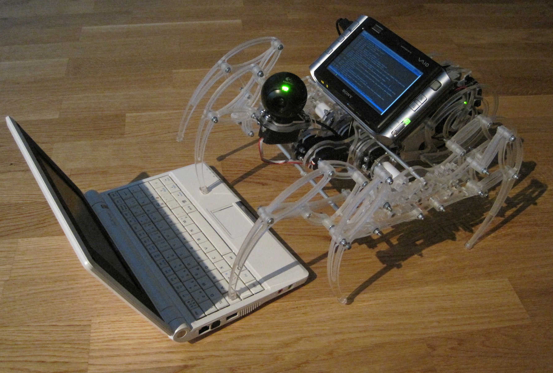
The Spider is a computer controlled robot with eight legs, machined of clear acrylic. On December 2009 I got my own desktop CNC mill and I was planning to launch a small-scale production of prototypes and made-to-order parts using it. Since I studied CAD/CAM at my university as a part of my studies, I already had some knowledge what it takes to make a mechanical part from the drawing board to reality but with no practical experience at all. I needed a project with which I could learn to use my CNC milling machine.
Browsing the Web, I found that someone had made an an eight-legged robot at Thingiverse.com which utilized a mechanical linkage system for locomotion. As this small mechanical spider, built partially of Legos and machined plastic legs seemed quite funny, I became interested in it and found the Klann Linkage, the mechanism that made it walk. After a little more searching, I found a web page of Joe Klann who is the inventor of the linkage. On his webpage I saw a mechanical spider machined using a benchtop mill out of aluminum. A little steam engine powered the small and beautiful mechanical device. This was so neat piece of machinery that I wanted my own too which led me inspecting the Steam Spider made by Crabfu and Klann more closely.
The steam powered mechanical spider was said to be under-powered but as one of my goals for this project was to test a First-person-view (FPV) system and a headtracker-controlled camera with a motion platform for future projects, I decided to use electric motors to drive the legs. The FPV system I installed in the spider was a test of WLAN video streaming and remote control, a system later to be used in a flying quad-copter drone. So these were the key ideas behind the project which made me spend hours in front of my PC and CNC mill. I wanted to learn CNC-machining and to create a eight-legged mechanical beast in the process while evaluating a camera and control system later to be used in micro aerial vehicles.
The FPV setup was replaced three years later with sensors that were easier to interface with the Arduino.
Designing the beast
When I saw a small mechanical spider implemented with the Klann Linkage, I began searching for drawings as I did not want to draw the thing from the beginning at the first place. However, I found nothing what could have met my needs, so I eventually ended up drawing the mechanical spider myself. While it made the project much more difficult, I learned a lot in mechanical design doing it – it is not as simple as it seems to make a pile of parts that attach each other and provide the required functionality.
Fortunately the webpage that introduced the Steam Spider, had few pictures with dimensions of the Steam Spider that were used in also my version. I used the dimensions found in those drawings as guidelines but as I wanted the machine look unique, I designed all the parts myself, trying to achieve a “natural” look. I wanted every part of the machine to look like a blend between a high-tech mechanical part and a body part of some creature.
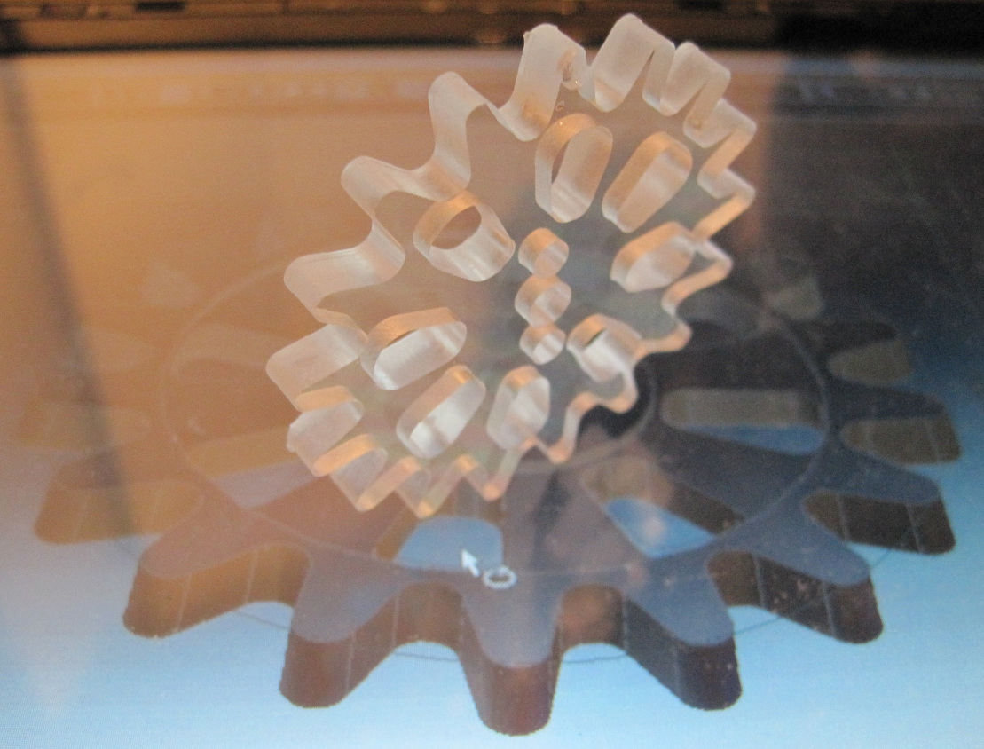
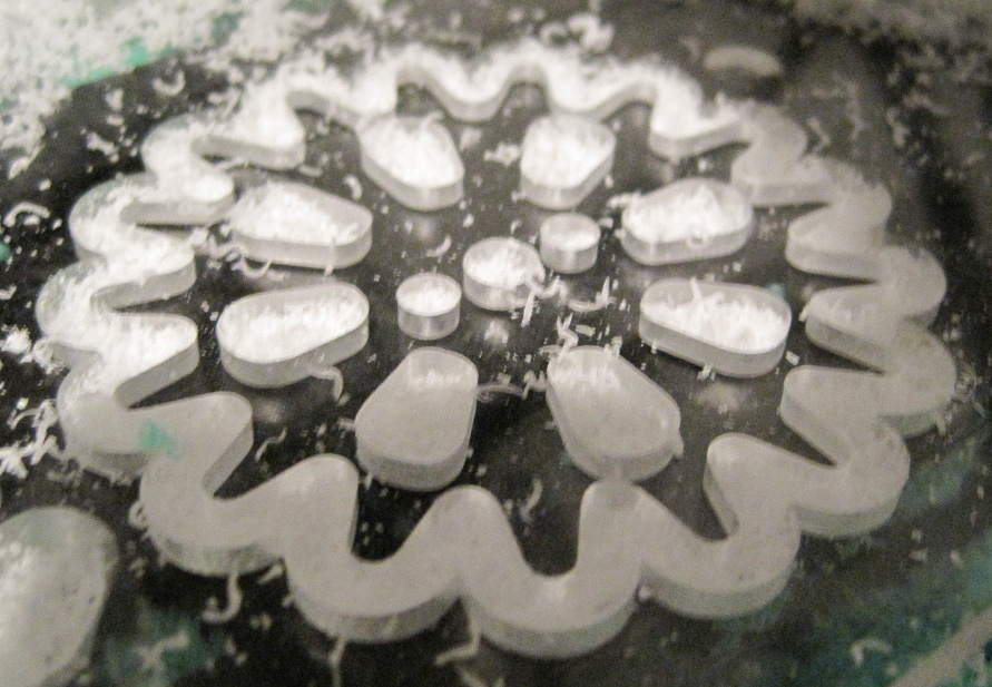
As the project consists of almost two hundred parts which are to be manufactured using a rather slow miniature CNC mill, I chose to make the spider out of transparent 5 mm acrylic. The sheets of acrylic are much more faster and easier to cut than aluminum.
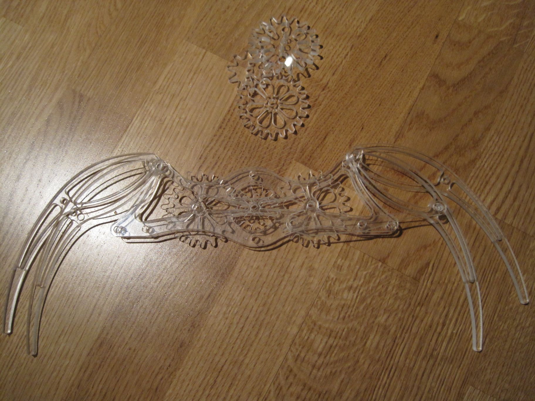
The parts of the spider feature curved lines and various holes to make the structure lighter in weight but also more detailed in the look. I did not want to have parts that are only cut from the acrylic sheet with no detailing. Designing the parts this way was time consuming but I learned a lot in the process. This was the most time-consuming task in the project. As I eventually learned, in mechanical design, drawing the geometry of the part is not the only thing to do. One must consider also how easy – or impossible – the part is to manufacture. Features that are too thin will break during the machining. Some features in the parts must be machined before the others and the capabilities of the machinery must be also taken in account in design. And when the part is completed, is it possible to attach it to the mechanical assembly, will it fit to the other parts, how one can fasten it and will it work as intended. These are the questions that must be taken in account when designing the part.
All the parts were designed using the Alibre Design Xpress after the initial sketches that were drawn using a pen and paper.
Machining the parts
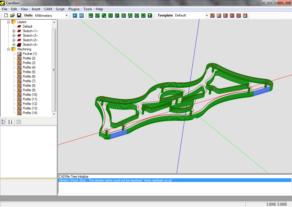
After a part of the spider was drawn at the CAD software, the next task was to machine it. The machining is done using computer-designed toolpaths, which the milling machine follows. For creating the toolpaths, I used the freely available CamBam software.
Designing the toolpaths requires knowledge of the capabilities of the machine and materials used. First of all, the correct milling order the features must be decided. One must not cut the part away from the sheet until every other feature of the part is machined. It is also preferable to design the parts so that they can be machined in a single pass with as little turns and re-attachments as possible, since precise alignment of the part and the machine is always difficult.
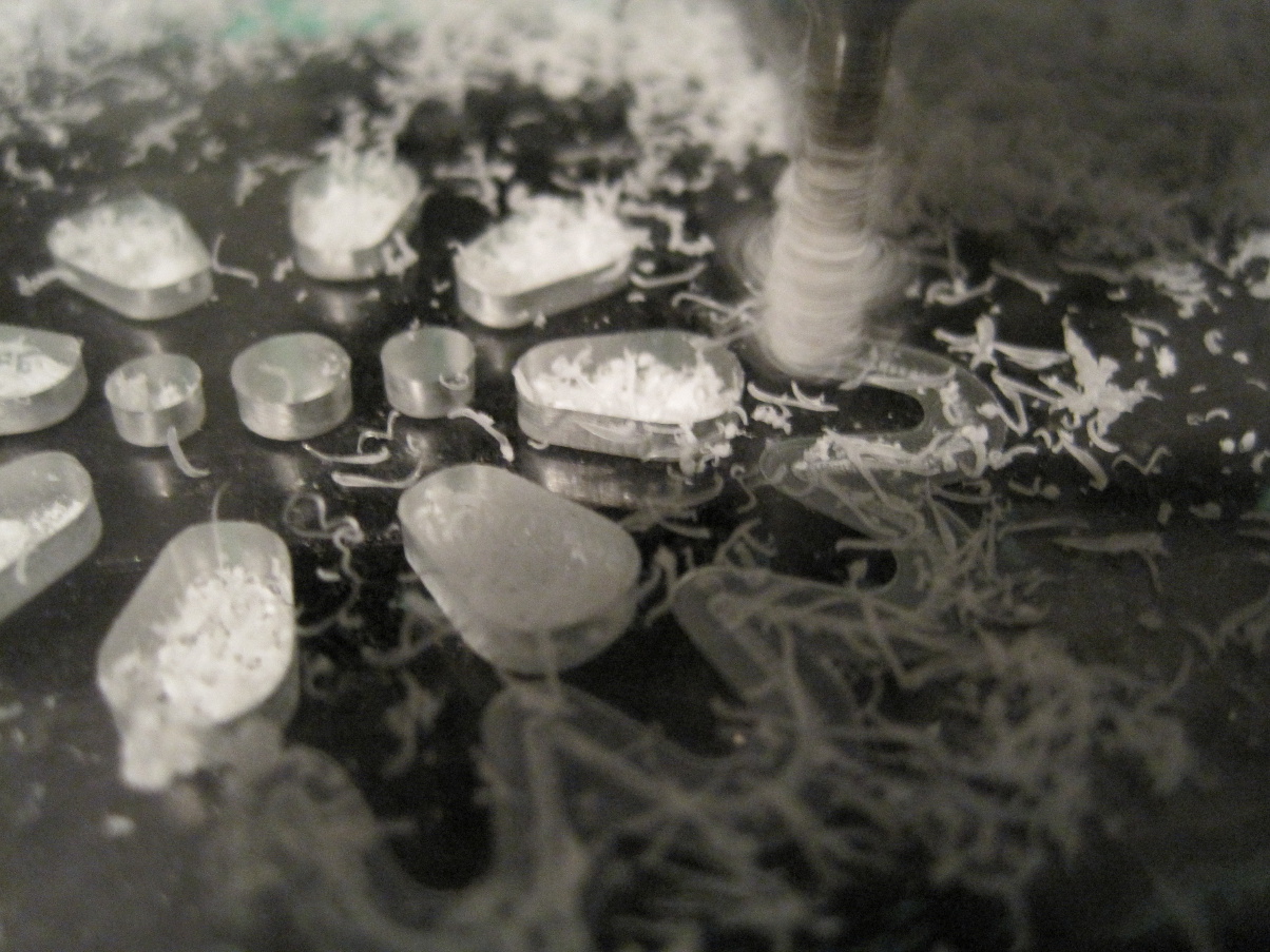
This was the first project for me with my Sherline Model 2020 benchtop CNC. The machine is capable of using endmills ranging from the fraction of the millimeters up to 9 mm in diameter. The larger diameter endmill is always more stable and less prone to vibrations which may affect negatively to the surface finish. The majority of the parts were milled using 3 mm and 5 mm endmills. The parameters that affect the end result most in terms of quality and manufacturing time are feed rate, milling direction and milling depth. While machining the spider, I learned a lot in choosing the parameters according the capabilities of the machine, tool and material used. This was a great way to learn making things with a CNC! 😉
Legs and the drive mechanism
Each leg of the spider consists of 5 unique parts. Eight legs need forty of them. The parts are attached into each other with screws and bushings. There are four bushings per attachment and many of the parts are mounted on two points. The bushings were first made of acrylic but I later machined them out aluminum for lower friction and quieter operation, using blind rivets as raw material. The total part count for the legs was well over 100 parts.
The legs are driven using a reduction gear, each side attached on a servo motor. The servos are standard Futaba 3003 servos which were modified for continuous rotation. I only needed the motor and that rather high-quality reduction gear set of the servo as the legs require more torque than speed. To enable continuous rotation, I had to bypass the feedback circuitry and remove the limiters which prevent servo gears turning 360 degrees. In the case of the standard plastic-geared Futaba servos, it was easy as all the tools needed were a sharp knife and a drill bit. The knife was used to remove the plastic limiters and the drill bit was used to remove the mount of the potentiometer shaft from one of the gears. The potentiometer provided the position feedback but also restricted the rotation of the servo.
The frame
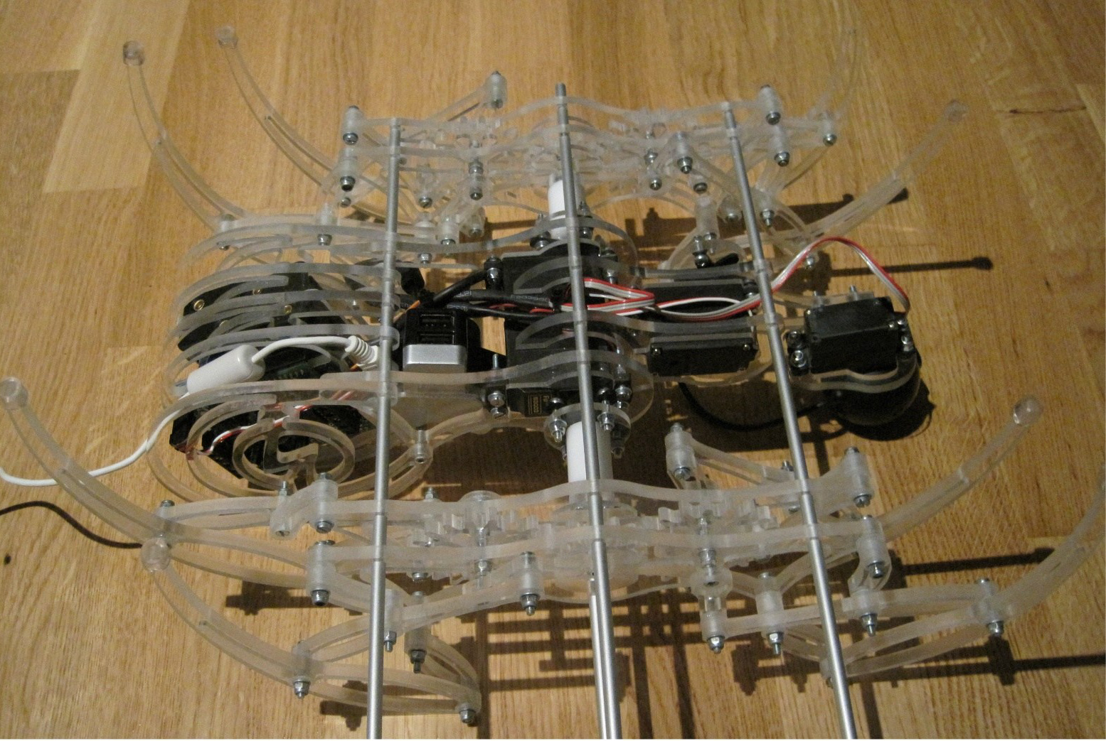
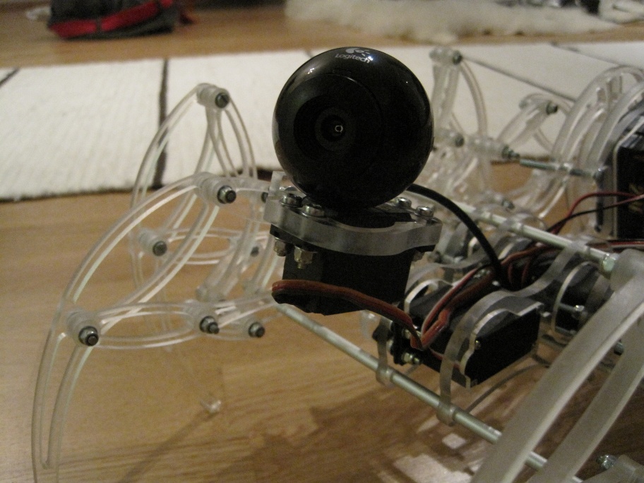
The frame which houses the servo motors and electronics was also designed so that it resembled the body of a real spider. It features round and smooth, natural kind of shapes. The legs are attached to the servos with short drive shafts which were machined out of polyacetal plastic (Delrin) which has very favorable maching qualities. The frame is held together with aluminum tubes which are held in position only by friction. The CNC milling machine made it possible to drill holes for the aluminum tubes that are so tight that the friction of the attachment is enough to hold the thing together. The rear frame of the spider was designed to house electronics while providing the spider-like shape. To keep curious hands away from the electronics, the read body features a large lightning bolt which I think is also a nice emblem for the electronic spider. The front part of the frame keeps the head tilting servo in place and serves as an attachment point for sensors in future.
Electronics
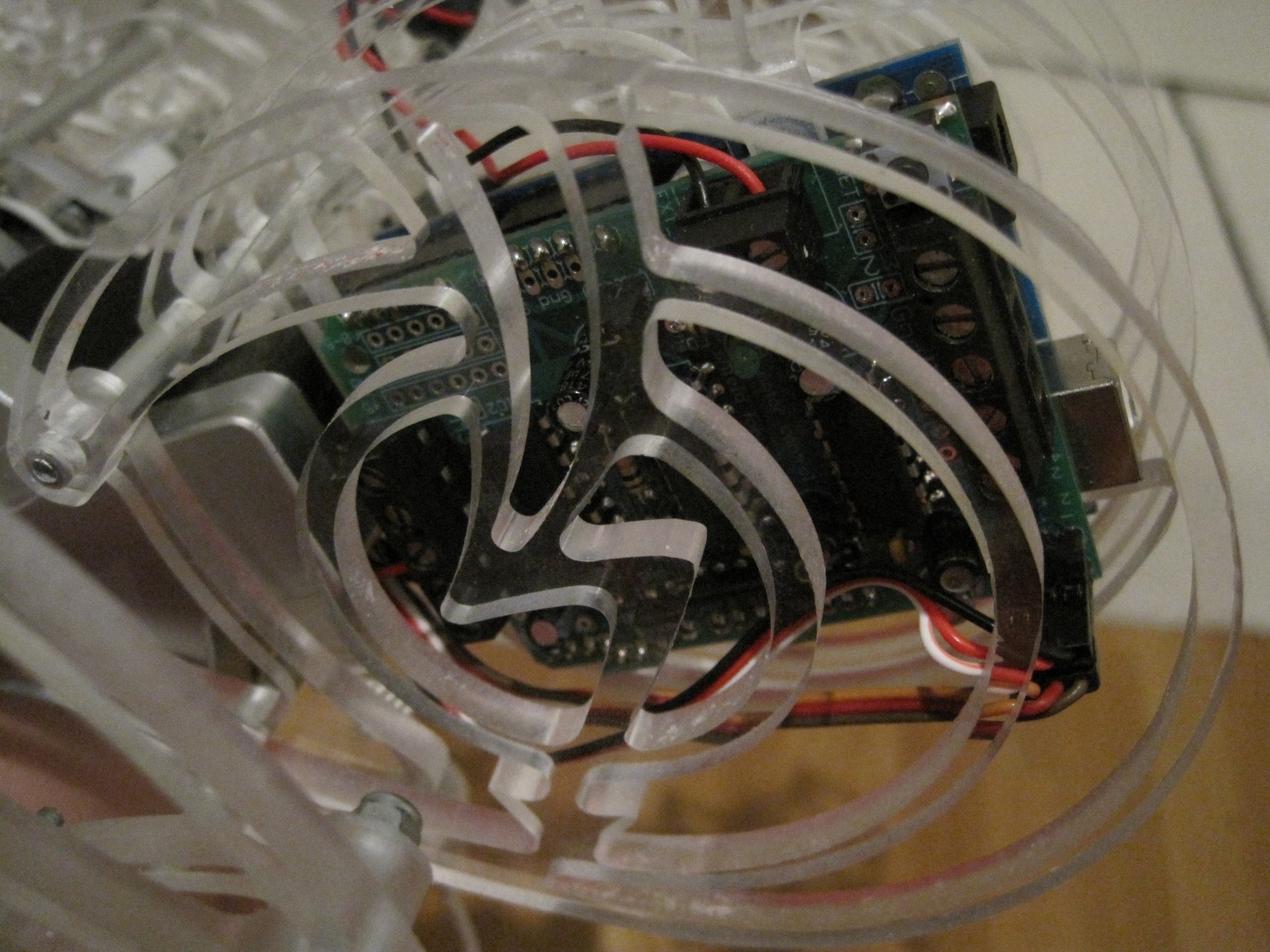
The spider has had two sets of electronics, for different purposes. The only common between these is the Arduino Duemilanove which is used for interfacing the hardware and Adafruit Motor Shield which drives the motors and servos.
Version 1 electronics, the FPV setup, 2010-2013
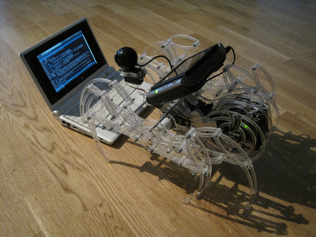
The first version of the electronics featured a wireless computer control with a video stream over WiFi. The Spider’s head had a Logitech web camera attached. The middle part of the frame housed an USB hub which also the Arduino was connected. The USB hub was then attached into a Sony Vaio UX380N miniature laptop which sat over the spider and ran the webcam streaming software and a custom-written Python software for interfacing the Arduino. The video was streamed over WiFi to a PC which was used for the control. This computer had virtual reality glasses with a headtracker was attached. The spider was controlled using arrow keys, while the headtracker controlled the servos.
This setup was used to test the feasibility of controlling devices with a video stream over WiFi, but was then changed to a more lighter setup. The weight of the computer and required hardware was too much, making the spider quite sluggish.
The power supply of the robot were eight AA batteries which also were quite heavy.
Version 2, accelerometers and sonars, 2013
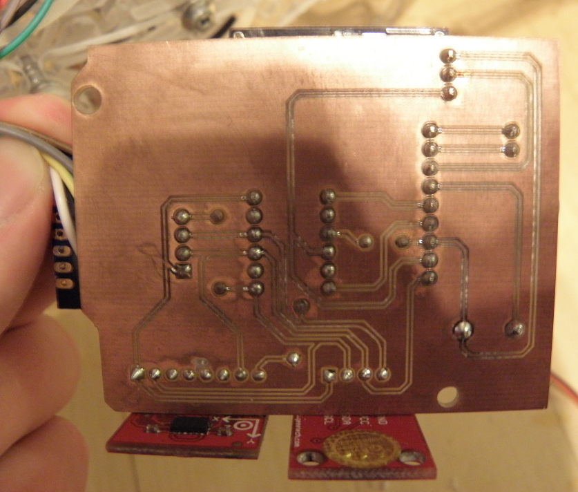
The weight and complexity of having a Windows Vista computer onboard, made me think of lighter alternatives for the control electronics. The Arduino and the Motor Shield mounted on the back of the spider remained, but everything else was made different. The web cam was replaced with a ultrasonic range finder. A custom-made circuit board featuring an electronic compass (Honeywell HMC5883), accelerometer (Analog Devices ADXL354) and a microphone was milled using the CNC mill.
These sensors made easier to program some interaction between the robot and the surrounding world, than using machine vision algorithms with a webcam. Currently the spider reacts in handling, taps, sharp sounds and so on. With the sonar rangefinder, it can avoid obstacles. The robot connects to a controlling computer via Bluetooth adapter.
The heavy battery pack was replaced with a small switch-mode power supply and lithium battery pack. These weight savings with new lower-friction bushings on the mechanism made the spider way more agile than the first version of it.
The software
Both of the versions have similar code and behavior. The software takes commands from serial connection and drives the servos and motors accordingly but in later version, it also takes surrounding world in account with sensors. The sonar mounted on the spider’s head with pan and tilt servos, scans the front sector and determines the obstacles that the spider tries to avoid. Different inputs like clap of the hands, taps and moving the spider, trigger various actions and gestures.
If no input is provided for a while, the spider begins to look around with its web camera or sonar which raises and lowers in a manner which resembles a breathing creature.
Conclusion
The lengthy project of creating this electro-mechanical monster taught me a lot. I learned that creating mechanical devices from scratch with special design features is not only challenging but also quite rewarding. I was able to evaluate the freely available software for computer aided design and manufacturing and select them that work best for me.
I also learned a lot about the workflow which is required in making things with computerized tools. The spider served also as and introductory course for the Arduino platform. The video link and head-controlled camera of the first version were quite unique, too. With them you basically sat inside the thing and could look around by rotating your own head. However, the cheap webcam used did not provide video good enough. In the quad-copter project that followed the spider I used a Playstation 3 Eye camera which provided 60 frames per second with no lagging or ghosting. Unfortunately the spider was a little too sluggish because of the weight of the equipment.
The Spider nowadays sits on a table in the corner of my living-room, full of sensors, intimidating everyone that goes by. It is also known to take occasional walks around my house when it’s dark, pondering its evil plans of global domination.