
Introduction
The Drone is my small quadrotor aircraft, first flown in 2010. As these devices first appeared in the mid-2000’s, I was completely sold when I saw videos of them, made by some big-money research lab, hovering still, controlled by their on-board computers. Back in the beginning of 2000’s, sensors and electronics were so expensive that I could not afford them. But when mobile phones and tablets that use small gyroscopes and accelerometers that are also suitable for flying machines became popular, the prices of the electronics came down, making these machines affordable.
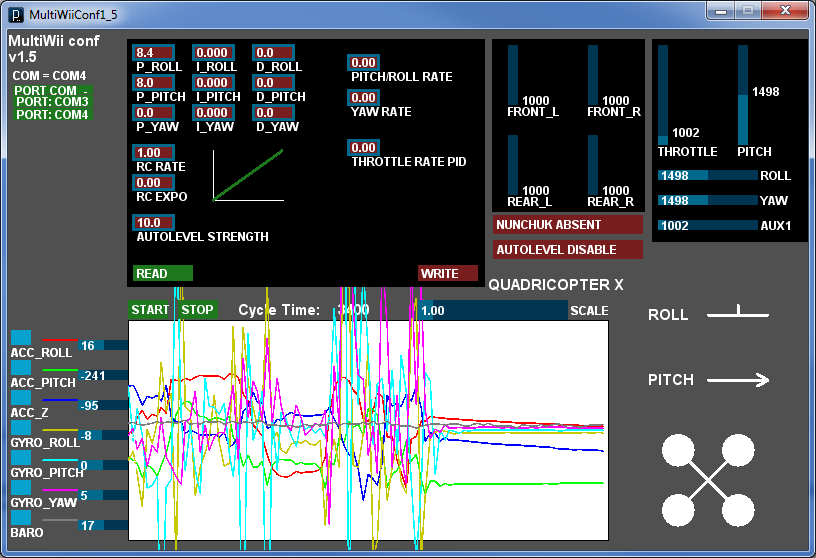
In the late 2010′s I was told by a Finnish multirotor enthusiast, nick-named Sambas that there was an open source flight controller project being developed which I might be interested in, known as MultiWii. Developed by Alexander Dubus, it was built around cheap and easily available hardware. The MultiWii, as its name implies, uses gyroscopes from Nintendo Wii and regular RC model aircraft parts to keep the project affordable.
Design features
The driving idea behind the whole project was that I wanted a flying development platform that is capable of semi-autonomous operation and which is also fun to fly.
The features I wanted to built into it or experiment with were:
- Video streaming for First-Person View piloting
- Capability for aerial photography
- Flying using machine vision
- Expandable for future needs and ideas
With these goals in my mind, I started designing the hardware for the Drone. All of the features above required a high-speed two-way data communications and some on-board computer hardware. As I wanted the fully digital video streaming and do all the processing within the aircraft, it became clear to me that I needed an embedded Linux computer system onboard the Drone.
The embedded Linux system made it also easy to implement a data communications link using WiFi. Instead of normal RC radios, the first versions of the Drone were completely controlled over WiFi. The WiFi also sent telemetry data and video stream back to the ground station. Unfortunately after some bad crashes, to increase the reliability of the Drone, I had to switch to analog video link and XBee data transfer. The software developed for the on-board computer still remains and runs on a ground station.
Mechanical design
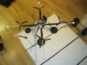
The most time-consuming task in the project was mechanical design. The Drone required a structure that had to be both lightweight and durable. The frame has to protect the electronics inside while isolating the sensors from mechanical vibrations from the propellers.
As the Drone was going to be an experimental device in many aspects, a lot of mishandling and crashing was to be expected which it had to withstand, being also as easy and affordable as possible to manufacture and repair. For this reason, all the hardware required had to be locally available.
The first versions of the Drone featured plastic parts made of acrylic, which were later replaced with parts made of impact-resistant polycarbonate and polyethene.
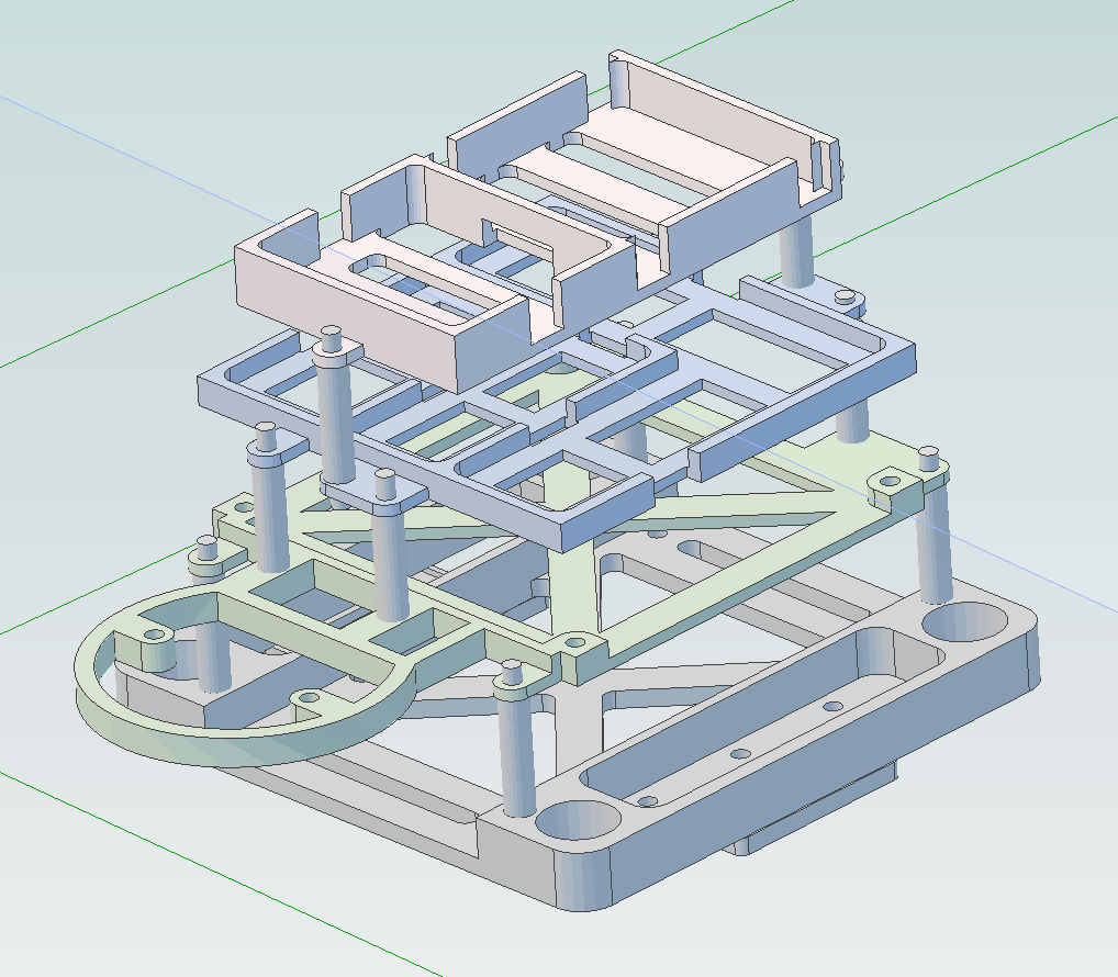
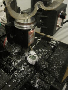
I designed the parts using Alibre Design Express. The geometry designed using Alibre was then transferred to the CamBam CAM software which creates tool paths for the desktop CNC mill. The Alibre is affordable, feature-rich CAD software which is perfect for projects like this one.
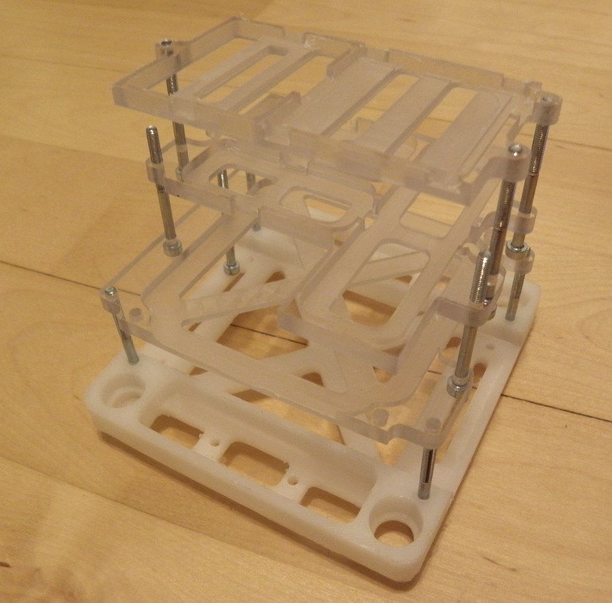
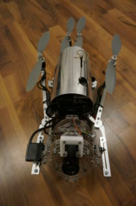
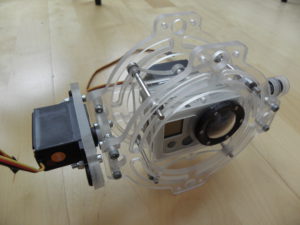
The first part I designed was the base plate which the whole electronics compartment is built on. The base plate is attached to the aluminum frame using rubber grommets made of soft vibration-dampening rubber. They help isolating the electronics mechanically from the aluminum frame. The vibrations from propellers will affect the sensors, making the drone unstable. The lithium-polymer battery will be mounted on top of the base plate, under the first layer of circuit board frames, well protected by the structure in case of crashes. The first frame on top of the base plate housed the BeagleBoard and the Sony PS3Eye camera which was later removed and replaced with a smaller, servo-tilted web camera. The first versions of the parts were deliberately destroyed to evaluate their strength and refine the design according to the results.
Motor to motor distance is ~60 cm. In later rebuilds, the frame was made smaller and stiffer, which helped to reduce the vibrations making the Drone fly even better.
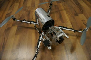
The final version of the Drone featured a revised inner structure with fully enclosed electronics compartment to prevent snow and dust entering the electronics. The insides of the machine are protected from impacts with a polished cover made of aircraft aluminum by two friends of mine who are aircraft mechanics.
Embedded Linux board

Choosing an emdedded Linux computer for the Drone was rather easy in 2010, due to small number of available options. The nowadays popular Raspberry PI, did not exist back then.
I selected the Beagleboard which was probably the most refined of these boards and I expected it to have the best software support of embedded Linux devices. I used a C4 revision of the board which had an ARM Cortex A8 CPU, clocked to 720 MHz. While the dual-core model, BeagleBoard XM, offered better performance, I found the C4 to suit better for my needs by its smaller size. The Beagleboard was not easy to set-up as the Linux distributions available for the board all had issues. While one had defective WiFi kernel modules and no package manager, some of the distributions targeted for the board were not even able to boot. The Beagleboard was later replaced by less complex, lighter and more reliable hardware. But this is how everything started.
When all the components needed were acquired it was time to put it all together which was probably the most enjoyable part in this project. The sensors were bought attached in break-out boards which were then wired together. Using break-out boards instead of one single circuit board made the construction modular. The sensors could be mounted more flexibly and replacing them if they get damaged or if better sensor becomes available would be easier.

The sensor break-out boards were enclosed inside foam balls and then attached to the polycarbonate frame using zip ties. The foam dampens the vibrations very effectively and helps keeping the temperature-sensitive sensors warm. The frames were then stacked on top of each other.
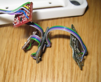
The wiring of the Drone took me few evenings. First the sensors were connected to each other, then soldered to the Arduino Nano.
After the sensors and Arduino was wired, it was time to connect the Beagleboard with the peripherals. The web camera, USB hub, WiFi USB stick and later GPS were modified and connected to each other. I removed all the USB connectors and wired the peripherals permanently to the USB hub. This was done not only to save weight but to provide secure connections, with no possibility for a loose connector. The USB hub was then connected to the Beagleboard. The electronics were throughoutly tested between each step.

I used a color-coded high-quality flat cable for wiring. The color coding helps in debugging if needed. All the soldering work had to be done carefully since only one bad solder joint could cause a crash destroying the Drone. The soldered wires were later secured with hot-melt glue which is not a neat solution by any means but it works. When all the electronics were connected, the result was a quite mess, with had to be tidied up with zip ties. It was essential to make sure that no wires were under load which could cause them come loose.
The electronics compartment is connected to motor controllers and other hardware using D9 connectors, located at the bottom of it. The connectors are secured using zip ties as screw mounts were difficult to implement because of their size. The upper D9-connector is used to power the electronics. It has a +12V input, Ground, USB connection for the GPS or mouse and keyboard and a camera trigger pin.
The USB hardware is connected using a adapter cable which also provides power for the electronics from a wall transformer without the need for batteries while testing and configuring the software. This way the electronics can be powered up and tested without energizing the motors which could cause damages in case of software failures. The lower connector has connections for four motor controllers and power supply and control lines for two servos of the stabilized camera mounts.
Inertial and Magnetic sensors
The MultiWii flight controller was built around gyroscopes and accelerometers of Nintendo Wii game controllers. Among the hobbyists building their own RC models it was a common practice to get the sensors required from the cheap clone Wii controllers from various Internet sources which ended up being a lesson about Chinese quality.
The clone Nunchuck which took weeks to ship, failed within two hours and the Wii Motion Plus gyroscopes had also some interesting properties. Values read from the gyro ranged from usable ones to values that were out of all the scales. The clone controller worked if the gyro chip on the circuit board was touched when powering up the board. When my magic touch was not present, nothing worked.
Lesson learned, I purchased a genuine Wii Motion Plus for the gyroscope, a Sparkfun ADXL345 Breakout board for the accelerometers and also a breakout board of the Bosch BMP085 pressure sensor for altimeter. Later a magnetometer was also added. A Sparkfun logic level converter board was also needed to attach these 3.3 volt sensors to an Arduino that runs on 5 volts. The sensor package was placed inside a ball of foam to isolate them from vibrations and was wired on the I2C pins of the Arduino Nano.
During the project, several manufacturers offered improved sensors with better performance which replaced the original sensors on the Drone with increased stability. The very fragile Nintendo Wii sensors were first replaced using an Invensense MPU 6050 combined gyro and accelerometer.
The MPU 6050 was among the best micromechanical sensors there was and it provided the best performance. Unfortunately it performed poorly when temperature dropped below minus 20 degrees which is common here in Finland during winter and sometimes during summer, too. So the last rebuild of the Drone is equipped with an ITG 3205 gyro, a BMA180 accelerometer and a BMP085 pressure sensor mounted on a ready-made multirotor controller card from Hobbyking.com which allowed a clean installation without any extra wiring. Despite of its cheap price, the board has been performed flawlessly for over an year. These boards were not available when the first versions of the Drone were made.
Sonar and GPS

While the GPS and Bosch BMP085 barometric sensor provide altitude and temperature information that is useful for higher altitudes, the altitude data was not precise enough for automatic landing. For this purpose an ultrasonic sensor was installed but later removed due to problems. I wrote a PID control loop for sonar-based altitude hold, but never got it properly tuned. The cheap ultrasonic sensor was too erratic in its readings. As I never got it working properly, I did not release the code.
The GPS module I used was an old Sirf II RS-232 -interfaced receiver I had. It was later replaced with a high-speed USB GPS with 10 Hz refresh rate from DiyDrones.com which was later discarded due to its defective design without an on-board battery and overall poor performance.
The GPS was first connected onto the Beagleboard which transmitted the coordinates to the Arduino running Multiwii. On later versions it was connected directly to the Multiwii using an I2C converter board. Both approaches caused the Multiwii to lock-up every now and then while flying, resulting in a few bad crashes and eventually the GPS being removed. The navigation calculations were too much for the 8-bit AVR.
Arduino Nano
The MultiWii software that keeps the thing flying, runs on an Arduino board, which is based on an Atmel ATMega 328 microprocessor with a custom software development environment for rapid software development. The Arduino comes in different versions where the most common were the large Duemilanove and its successor Arduino Uno. I selected the Arduino Nano board because of its integrated FTDI USB-to-serial controller and small size. The Arduino Nano, produced by Gravitech, is basically a tightly-packed version of the Arduino Duemilanove, featuring a multi-layer circuit board to save space. One thing that should be noted when using the Arduino Nano is that earlier versions of it came with a small hardware bug. The FTDI chip onboard is wired incorrectly which makes the USB to serial bridge behave like it is broken. However this is easy one to fix, by soldering the TEST pin of the FTDI chip to the ground, but it took me quite long to find out what was wrong as the Arduino’s USB connection was unreliable. More information about the issue can be found here: http://www.arduino.cc/cgi-bin/yabb2/YaBB.pl?num=1263958401 Newer versions of the board are be shipped with these two pins wired correctly, without problems.
Radio modem
After experimenting with the WiFi control and data link and after few bad crashes, the WiFi and the onboard Linux computer were replaced with a long-range XBee Pro radio modem. The XBee modems provide a transparent serial link from the Drone to a ground station computer with a sufficient range. I managed to get bunch of these modems on eBay for affordable price. Nowadays the Drone is controlled using RC radios, with a possibility for computer control over XBee data link. All the telemetry is sent back using the XBee.
Cameras
Choosing the suitable camera equipment for the Drone was not easy. The Drone had to be capable of streaming live video and taking rather good quality aerial photos. It would have been temptating to use only one camera to accomplish the both, but due to technical limitations this idea was soon forgotten. Not so long ago, digital pocket cameras were equipped with a feature that allowed them to be used as web cameras. During recent years, manufacturers have began disabling this feature for some reason, maybe promoting the sale of the more expensive DSLR’s or something. This was the case also with three digital cameras I planned to use with the drone. None of them were able to stream video over USB, even with a hacked custom firmware. One way to go around this limitation would have been a USB video capture card, attached to the Beagleboard and the camera’s composite video output. However after searching the Web for a while, I found that Linux support of these devices was not something to write home about. So this approach was forgotten for good.
As the easiest way was to get a normal USB web camera, I began searching for a suitable one, only to find out that most of them are not capable of delivering sharp picture without motion blur. However, there was one particular camera which was built around a high-speed imager chip, the PS3Eye camera of Playstation 3 game console. The PS3Eye was capable of shooting video at high framerates without blurring, it is supported in Linux and it comes with a price tag of under 40 euros. And it could be bought everywhere, such as from my local supermarket. The PS3Eye was widely used in machine vision experiments and it was the best camera for a project like this.
Streaming video
1. The PS3 Eye
For the first versions of the Drone, the PS3Eye camera was selected for the first-person flying and camera aiming. The PS3Eye is widely used in machine vision experiments because of its high refresh rate and sharp picture in demanding low light conditions. The video does not blur in rapid movements or in low lighting conditions. The fast speed is achieved using uncompressed video stream. Prior sending it over WiFi, it had to be compressed which used too much resources on the Beagleboard on the Drone which in turn made undesirable delay to the control link.
2. Creative Labs’ HD Camera
The PS3Eye was later replaced with a Creative Labs’ HD-capable web camera that compresses the video using on-board encoder, reducing processing power requirements. Unlike the PS3Eye, it sent MPEG4 -compressed video. The camera had some unfortunate compatibility issues under Linux and only few resolutions, frame rates and exposure settings were supported, which made it very picky of lighting conditions. Almost there but far from perfect.
3. Minoru 3D
The Minoru 3D was a web cam with two lenses and sensors, combined using an internal USB hub. I got two of these very cheap so I decided to try them out. While they looked nice, their performance was disappointing. The image quality was poor and it had problems with varying lighting conditions. Transmitting the video in 3D required too much power and bandwidth.
4. Analog Sony CCD Super HAD II
This is the camera that was selected in the final rebuild of the Drone. It is a completely analog camera, designed for surveillance applications. It copes very well with demanding lighting conditions and outperforms every webcam I have tested. Being analog, it requires an analog video transmitter but as the final rebuild of the Drone had no on-board computer, using the analog transmitter was not a problem.
Aerial photography and videos
In addition to streaming live video, the Drone had to be capable of taking rather good quality photos and videos. Several cameras was tested before I settled with its current camera, Contour Roam. Flying the DSLR cameras was out of question, as this experimental platform was far from reliable enough for them.
1. The Canon Ixuses

The first camera mounted on the Drone was Canon Ixus95 I had. As Canon cameras no longer support remote control, I used the CHDK software to implement interval-shooting feature into it. The CHDK, Canon Hack Development Kit, is a firmware modification that enhances the camera with several nice features. Features provided by the CHDK are RAW shooting, advanced adjustments and a scripting support.
The scripting support makes it possible to control camera using BASIC scripts such “10 print “hello world”, 20 shoot, 30 goto 10”. The image quality of the Ixus was OK, but I managed to destroy the camera by poor piloting. After I had collected all the parts of the Ixus 95 and tried to repair it with no success, I bought another Ixus. This was also enhanced using CHDK. My new camera lasted for approximately two weeks and it met its demise when the Drone crashed due to issues in the control link.
2. An old Canon PowerShot
After destroying two new Ixuses, I decided to try a old Canon PowerShot with remote control capabilities. I connected the camera to Drone’s on-board computer using USB and wrote a nice Python scripts to remote control the camera using the Xbox controller I use to fly the drone. The scripts adjusted the camera settings, shot photos and transmitted the image taken to the controlling device. I flew with the PowerShot few times, but it was discarded because of the image quality. The old PowerShot had no image stabilizers which made the images awfully blurry if the camera is not absolutely stationary during exposure. The Drone software has the PowerShot support still built in for future use.
3. The GoPro HD Hero 2
Being the most hyped action camera ever, the GoPro is a small wide-angle action camera which is used by extreme sport enthusiasts. The camera was a complete disaster. Poor image quality, highly unreliable. Never again.
4. Contour Roam
The Contour Roam is a rugged action camera built on the Ambarella’s chipset and imaging sensors like all of the similar products on the market. The Roam ended up being a final camera of the Drone, and I am very satisfied in its price-to-quality ratio. The Roam can be hacked to shoot smooth 60 FPS video by uploading a firmware of the later Roam 2 to it.
Motors and speed controllers

The Drone is powered using four brushless outrunner motors, used in model aircraft. The simple and light construction makes them reliable and very responsive. As the multi-rotors vary the engine power setting at frequency over 400 kHz to achieve stability, the motors must be able to keep up with it.
The motors are controlled using 30 amp motor controllers that are used in model aircraft. Those are small three-phase inverters that use a small 8-bit AVR microcontroller. The motor controllers are programmed to introduce a little delay in motor control to smoothen throttle commands. As these motor controllers are normally used with model aircraft or helicopters with a reduction gear, the smoother throttle response reduces mechanical load on the reduction gear. The MultiWii software can cope with the delay but less the delay the more stabile the aircraft is.
A while ago, an updated firmware for a selection of speed controllers was developed by hobbyists. This firmware is developed for use with the multi-rotors and it eliminates the delay from the motor control. While it is possible to use unmodified speed controllers with the MultiWii, the modified responsive firmware greatly enhances the stability of the multi-rotor as can be seen on videos below.
The motors spin 12-inch fiberglass-nylon composite propellers with 3.8 inch pitch made by APC. Two of them rotate in clockwise direction and two of them are counter-clockwise to compensate the torque. The Drone’s yaw axis is controlled by varying the speeds of opposite motors and resulting torque.
The Drone with modified motor controllers
Unmodified motor controllers
Software

The software setup of the Drone consists of a server software, a client-side data link software and virtual cockpit software, each sharing their data over TCP/IP.
The MultiWii is modified to accept control commands over serial link from the control server while providing a telemetry data. The control software is written in Python using Pyro network library and PyGame for visualization. The software was developed using a PC and then transferred to the Drone’s Linux system. The modular server-client approach makes it possible to integrate various high-level control interfaces and features such as machine vision to the Drone’s avionics. The software setup is illustrated in graph. The final rebuild of the Drone differs from the graph so, that the server side software runs also on a ground control computer instead of an on-board one, with a XBee uplink for better reliability.

Ground control

As the Drone’s software, except the one that Arduino runs, are written in Python, almost any device can be used to control the Drone. The controlling devices can range from a cell phone to a full PC, as long as the device is capable of running a Python interpreter. This page tries to describe the various hardware which is used to fly the Drone.
The software development started on a laptop PC running Windows which I also planned to use to fly the Drone. The first flights of the device were flown using F-15E fighter jets replica flight stick and throttle grip. While it was a rather nice way to fly the Drone, after few trips to the local airfield with all this equipment, I began searching for something more lightweight and compact, ending up using a XBox 360 controller with modifications.
The XBox 360 controller has two analog sticks, two analog triggers and a bunch of digital buttons which is more than sufficient. The Drone has its roll and pitch axis controlled using the right stick, throttle is controlled with the modified left stick. Rudder is controlled using two analog triggers. The Start button arms the motor controllers. Stop button disarms the motors. The “shoulder” buttons are used to switch settings pages and colored buttons manipulate the menu system of the flight control software.
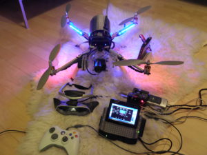
The XBox 360 controller can be used with Nokia N900 smartphone and Sony Vaio UX 380N ultra-portable computer. I used the N900 for a while but nowadays I use the Vaio with a high-capacity battery, because of its computing power.
Video stream from the Drone can be viewed from the display of the Vaio UMPC which however is difficult to read in daylight. For flying, I sometimes use the Sony Glasstron PLM-S700 virtual reality glasses, equipped with a headtracker. The Glasstron is a quite rare head-mounted display from the beginning of the 2000’s, with quite good image quality and ergonomics.
All the equipment needed to fly the Drone are mounted inside a Pelicase-like waterproof rugged plastic case. An aluminum frame was made inside the case where the electronics and batteries are attached using velcro straps.
Versions
Since its first build, the hardware of the Drone has changed significantly.
This is not only because of the crashes and rebuilds, but also thanks to advantages in sensor technology.
2010-2013
The first build of the Drone on 2010, had the following features:
Onboard computer: BeagleBoard C4
Flight controller: Self-made, using Arduino Nano as a base, with sensors and other hardware wired onto it.
Software: Self-made control and communications software, flight software based on MultiWii 1.8 with modifications.
Communications: WiFi
Sensors
Gyroscope: Nintendo Wii Gyroscope (Two analog Invensense sensors with interfacing done on a Nintendo-specific chip, on 2012 changed to MPU 6050)
Accelerometer:Analog Devices ADXL345
Barometer:Bosch BMP085
Magnetometer:Initially none, later various Honeywell magnetometers
GPS:SIRF II-based (not used for navigation), changed to DiyDrones’ GPS.
Speed controllers: Hobbyking SS30A
Motors: Turnigy 2217, 860 KV
Batteries: Turnigy 12-volt (3S), 3300-4000 mAh
Cameras
Streaming video: Sony PS3 Eye (Later Creative Labs webcam, Minoru 3D)
Photos: Canon Ixus (Later Canon Powershot and a GoPro)
2013
After many minor crashes and rebuilds during the development and flying, I eventually had the Drone almost completely destroyed because of a control link and failsafe problem. In the late 2012’s, the Drone refused to be controlled while in flight, climbed to 20 meters and when my partially working, three-stage failsafe entered its final stage that powers the machine down completely, it fell on asphalt. The two earlier stages that reduce power for landing, were commented out during testing in the code, and I never remembered to un-comment the lines affected. All the electronics were damaged, so I had to rebuild them from scratch. Due to various problems and glitches related to the onboard Beagleboard and WiFi, I replaced the on-board processing with a XBee data link, and moved all the Python software to the ground control PC with an analog streaming video. Standard 35 MHz model aircraft radios are used for control, but the Drone can still accept controls over the XBee from the control software if needed for example machine vision experiments and like. I selected 35 MHz frequency because I wanted the 2.4 GHz to be free of any possible interference. This ended up also being the final form of the Drone.
Onboard computer: None, replaced with a XBee Pro datalink
Flight controller: Hobbyking MultiWii 328P, similar to my previous self-made hardware.
Software: Self-made control and communications software, flight software based on MultiWii 2.0 with modifications.
Communications: 35 MHz RC radios, 2.4 GHz XBee Pro, 5.8 GHz low power video transmitter
Sensors
Gyroscope: ITG 3205
Accelerometer: BMA180
Barometer: Bosch BMP085
Magnetometer: HMC5883L
GPS: None
Speed controllers: Hobbyking 30A Blue Series, modified with SimonK firmware
Motors: Turnigy 2217, 860 KV
Batteries: Turnigy 12-volt (3S), 3300-4000 mAh
Cameras
Streaming video: Sony Super HAD II CCD
Photos: Contour Roam with modified firmware
Conclusion
Back in 2011, the Drone was very advanced. There were no similar commercial machines available, the Parrot AR.Drone being just published to the market while my drone flew its first flight. The AR.Drone was very similar feature-wise, having an on-board Linux computer and digital video link – with the exception that my drone was not developed commercially by a large team of developers. This project was my first touch in this industry that has taken the world by storm in 2015 and 2016. I learned a lot about everything making it involved, from computer aided design and manufacturing to embedded Linux systems, of which this blog only scratches a surface.
Nowadays the drone industry has developed so fast so massive, that in 2016 there is very little room for own development any more. But it sure was fun to be ahead of the development for a short time, and the Drone – which also helped me securing some jobs – will remain in my collection reminding me what a passion to develop something extraordinary gave me back then. 😉