Introduction
This was a project where I attempted to upgrade my laptop with an integrated graphics card with better graphics hardware to run flight simulators with improved visuals and frame-rate.
As my previous experiments to bring more immersion to flight simulators, like the Sony Glasstron virtual reality glasses with a self-made head-tracker, required more graphics performance in order to provide smooth game-play, I started to search for different ways to upgrade my laptop.
During the last few years various products for external notebook graphics solutions have been introduced but none of them have entered mass-market. They are quite expensive and there are difficulties in both availability and compatibility. As I searched the Web for these, I found a thread at (defunct in 2023) Notebookreviews.com where enthusiasts have found out a way to manufacture an external GPU for laptops using commercially available parts. The thread got my interest and after couple of evenings spent by reading it, I decided to try to make one myself. And this is what this blog post is all about! 😉
Attaching a desktop graphics card to a notebook computer
The GPU is attached to the notebook using the XpressCard connector. The XpressCard provides a PCIE 1X -bus externally available for use with various peripherals. An alternative for the XpressCard slot is to use the internal PCIE -slot found in laptops, usually occupied by a wireless network card, but the XpressCard is more comfortable to use as an external expansion slot.
The first step was to get an adapter card which converts the XpressCard into the PCI-E. The adapter can be purchased directly from its manufacturer, at http://www.hwtools.net/Adapter/PE4L.html. There are two versions of this, the PE4L being an X1 -adapter. The PE4H is capable of providing a X2 1.0 bus which in turn provides better performance but requires more specific things from the notebook. As the chipset in my laptop does not support the X2 -link, I chose the cheaper PE4L. The adapter arrived to Finland within a week from Taiwan.
Then I had to choose the graphics card for the project. As said in the thread Notebookreview.com, the Nvidia cards provide best performance in bandwidth-limited operating conditions. The drawback however, is their high power consumption which also leads to high operating temperatures. As I did not have a sufficient power supply to drive the power-hungry GeForce cards, I decided to choose a Radeon-based accelerator. The GPU I was interested in was the HD-5750, mainly for its low power consumption and good price to performance ratio. The card I ended up with, was the Sapphire Vapor-X with enhanced cooler design and good overclocking capabilities. The card was recommended for me by Jouni Vasama of Metku.net.
As the card arrived, I plugged it into the adapter and tested it with my laptop, running Windows 7. The card was automatically recognized and Windows downloaded drivers for it automatically. It was all that was needed to do for the installation, the card worked perfectly without any problems. After few test runs with various games and flight simulators, I ran 3dMark 06 to get some figures of the performance. The card churns out 6900 3dMarks in my setup. The Radeon 5750 is said to be capable of providing ~15 000 3dMarks in optimal configuration but for me, the transition from original ~300 3dMarks provided by the integrated GeForce 6150 to the Radeon’s ~7000 3dMarks at less than 200 euros indicated a very successful budget upgrade.
Hardware modding
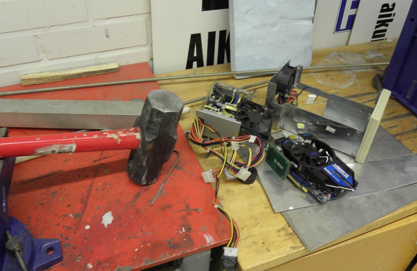
After playing with the card a little, I began making an enclosure for it which was a part of the fun in this project! As I meant this to be a budget upgrade which I could use also as learning piece for CNC machining, I set my goal: I wanted to create a neat-looking, finished external graphics adapter for less than 200 euros, including the graphics card. With this in mind, I started to sketch the case and search for parts. The low budget was made possible due to the fact that I had some spare electronics available for the project.
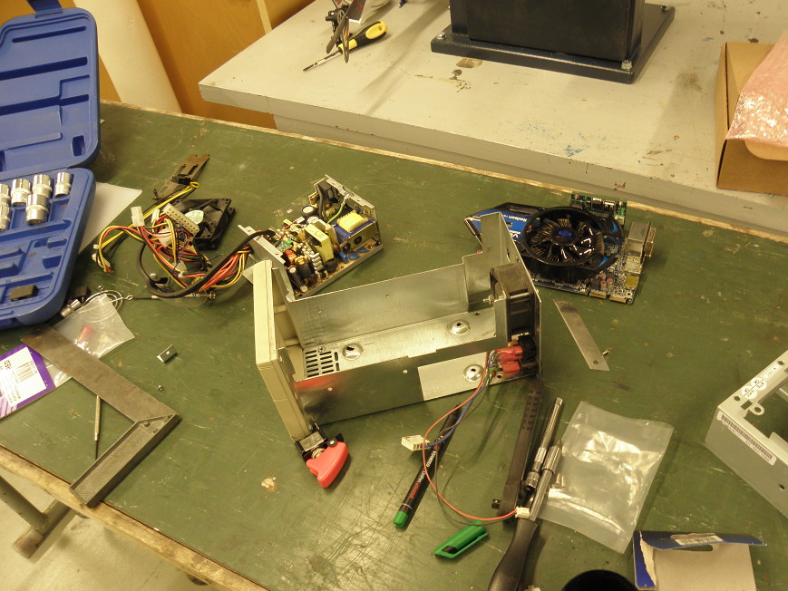
The enclosure I used as a starting point was an old, external SCSI hard drive which had been gathering dust in my house for a while. With a rotary tool, I modified the enclosure so that it could house the graphics card and the power supply.
Mounting the power supply
My original plan was to use a Fortron mATX power supply I had lying around but during my hacking I managed to damage it somehow. After crafting mounts and bolting it to the enclosure, I found out that it would not start up any more. As power supplies are rather cheap, I discarded the Fortron without attempting to repair it myself (my insurance company certainly would have not liked me tinkering it) and replaced it with a small FlexATX-power supply from an outdated Shuttle mini-PC. As it was smaller, it was a way more easy to mount than the Fortron.
I made a small mounting bracket for the PSU with cut-outs for an exhaust fan and power cord of 3 mm white acrylic with my Sherline bench-top CNC mill. The PSU is mounted to the enclosure with the bracket. It is also suspended from its side with a screw so it will stay firmly in place.
Mounting the graphics card into the enclosure
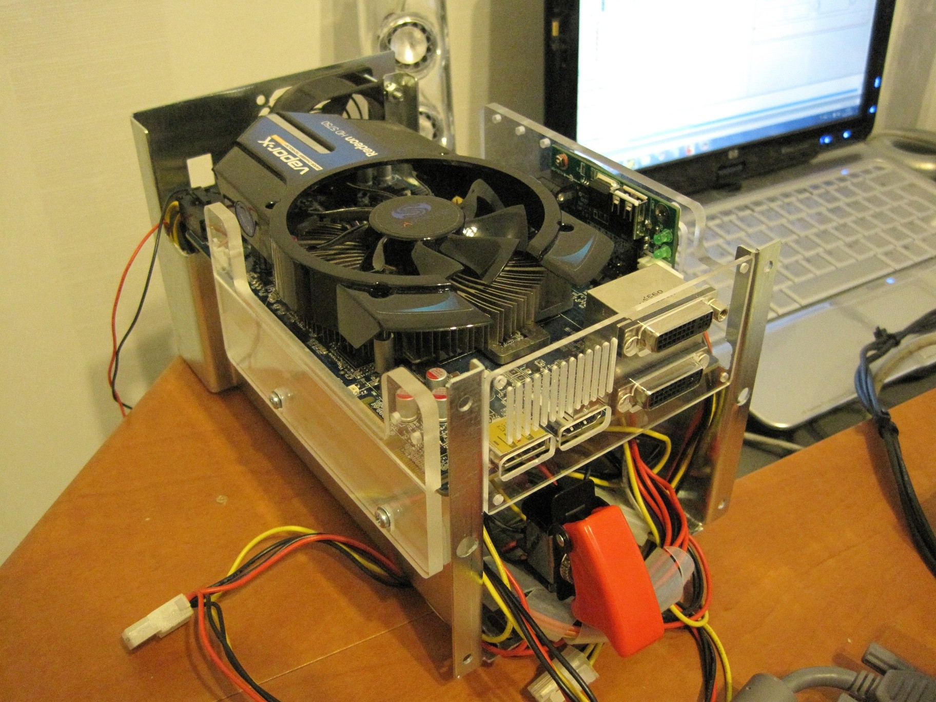
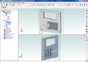
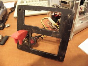
After few evenings spent with the CAD, I made mounting brackets for the adapter board and the graphics card. I also had to make a new I/O -panel for the card since the original metallic one did not suit my needs. The mounting brackets for the card were made out of 3 and 5 mm thick acrylic. The card is attached to the frame using the PCI-E adapter and a mounting bracket behind it. It is secured in place with the custom-made I/O -panel and a supporting bracket at the opposite edge of the card. Designing the mount required several attempts. The finished box features a slightly different mounting brackets that are seen in the picture.
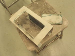
As in a some strange geeky sense, the graphics card with its huge fan and a futuristic-looking heat sink looks quite neat, I decided that it could not just be hidden inside the enclosure. So I cut a small window for it which also helps in cooling.
The cut-out was made using a rotary tool with a bunch of small cutting discs. The rounded corners were made using a small sanding bit and finished with a set of files. As seen in the photo, I first thought that a non-rectangular window would look nice but then I realized that achieving a neat, finished cut with the tools available would have been too difficult.
The front panel
The most difficult item to manufacture was the front panel. As the main purpose of the device was to run flight simulators, I wanted it to look like an old piece of avionics.
After numerous of drawings and sketches, I ended up with the current design. My first idea was to mill the front panel out of aluminum but I ended up with a part made of 5 mm thick acrylic. I prefer the acrylic since it is easy to machine and economical. The scrap pieces cost next-to-nothing at my local hardware store.
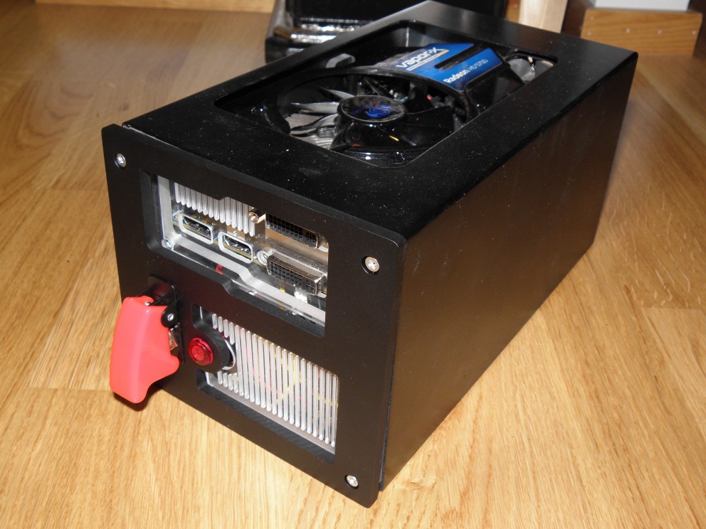
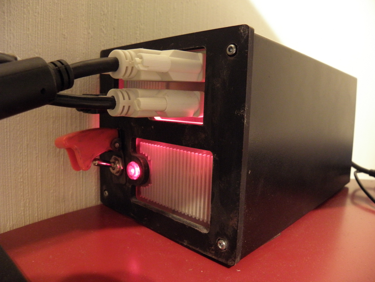
After milling the parts out of acrylic sheet I coated the foremost part of the three-piece panel with matte black paint. After the base color dried, I weathered it to look like an old metallic plate. Chipped paint, dirt, rust.. a proper doomsday device is nothing without a little signs of wear and tear! 😉
Other parts of the panel were sanded matte white with a rubbing pad to prevent all the wiring showing up. The acrylic plate behind the main panel was illuminated with three red LEDs, to provide a light strip next to the graphics card’s I/O -panel. The power switch for the box is a safety switch I found from local car parts store. I think it adds a nice finish to the military look of the graphics accelerator. The safety switch was installed with a red power light which were also weathered to look like rusty and dirty.
I wanted to use a regular light bulb instead of LEDs here for the look. The panel was then wired and attached to the enclosure with hexagonal screws that are sunk partially to the front panel.
After finishing the front panel, I wired up the switches, the front panel illumination leds, power supply for the GPU and the exhaust fan. The power switch is wired directly to the ATX connectors power-on pins and the 12-volt light bulb is powered from the five-volt line to make it dim. The front panel leds are also illuminated with five volts.
Finishing the accelerator
After completing the wiring I made some finishing touches such as the protective grille/window for the graphics card to prevent foreign objects entering the cooling fan. The window was the most time-consuming part in the whole project.
Designing it took few evenings with the Alibre Design Express. Machining time for the part was few hours with my small CNC mill. And I even had to make two of them since I made some mistakes with the first part. I used small round Dremel bits for the cutting since I did not have proper small end-mills available. The Dremel bits are not suitable for complex CNC milling, they tend to snap in half under load. But after few hours and three Dremel bits later the window was complete. It is attached to the box using strips of velcro. I decided to leave the window transparent so that the Radeon is clearly visible.
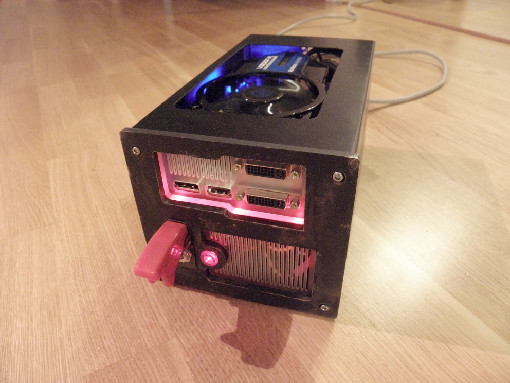
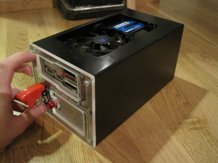
Completed GPU
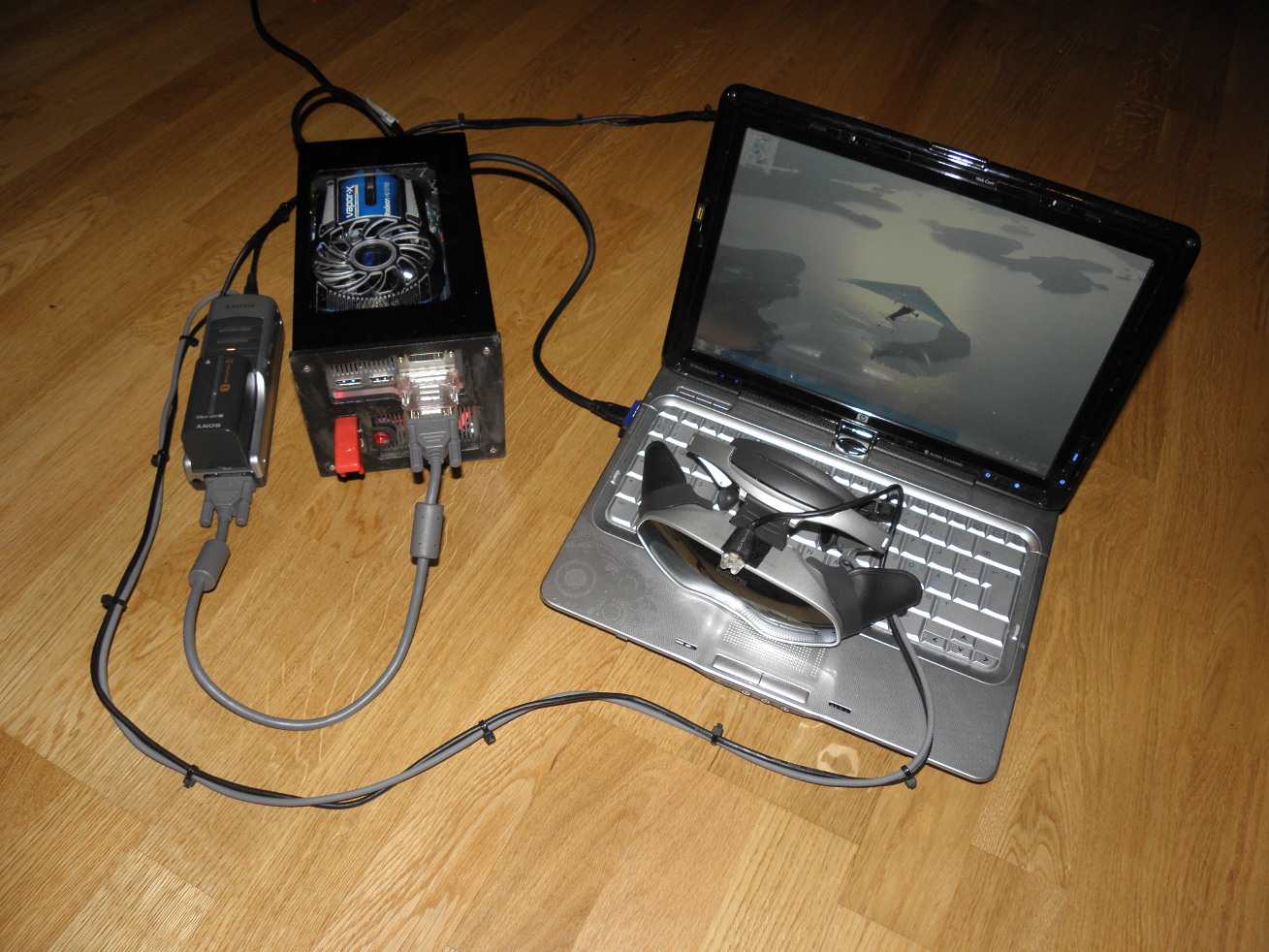
The result of the project was an external GPU that has served for three years at the time of writing this. The planned 200 eur limit held and I learned a lot in computer-aided design and manufacturing. It was fun to build and the device performed fine.
While this upgrade is something I would recommended, it is worth knowing that compatibility between different notebooks is almost a matter of trial and error. Due to differences in hardware and BIOS software of different laptops, some problems may exist with some computers.
Almost four years later, in the end of 2013, the device is still in use, driving my triple-display setup.
Software used in design and manufacturing (all freely available)
CAD: Alibre Design Express, Inkscape
CAM: CamBam Beta
CNC machine control software: EMC2
Thanks to
Notebookreviews.com forum writers
Jouni Vasama of Metku.net